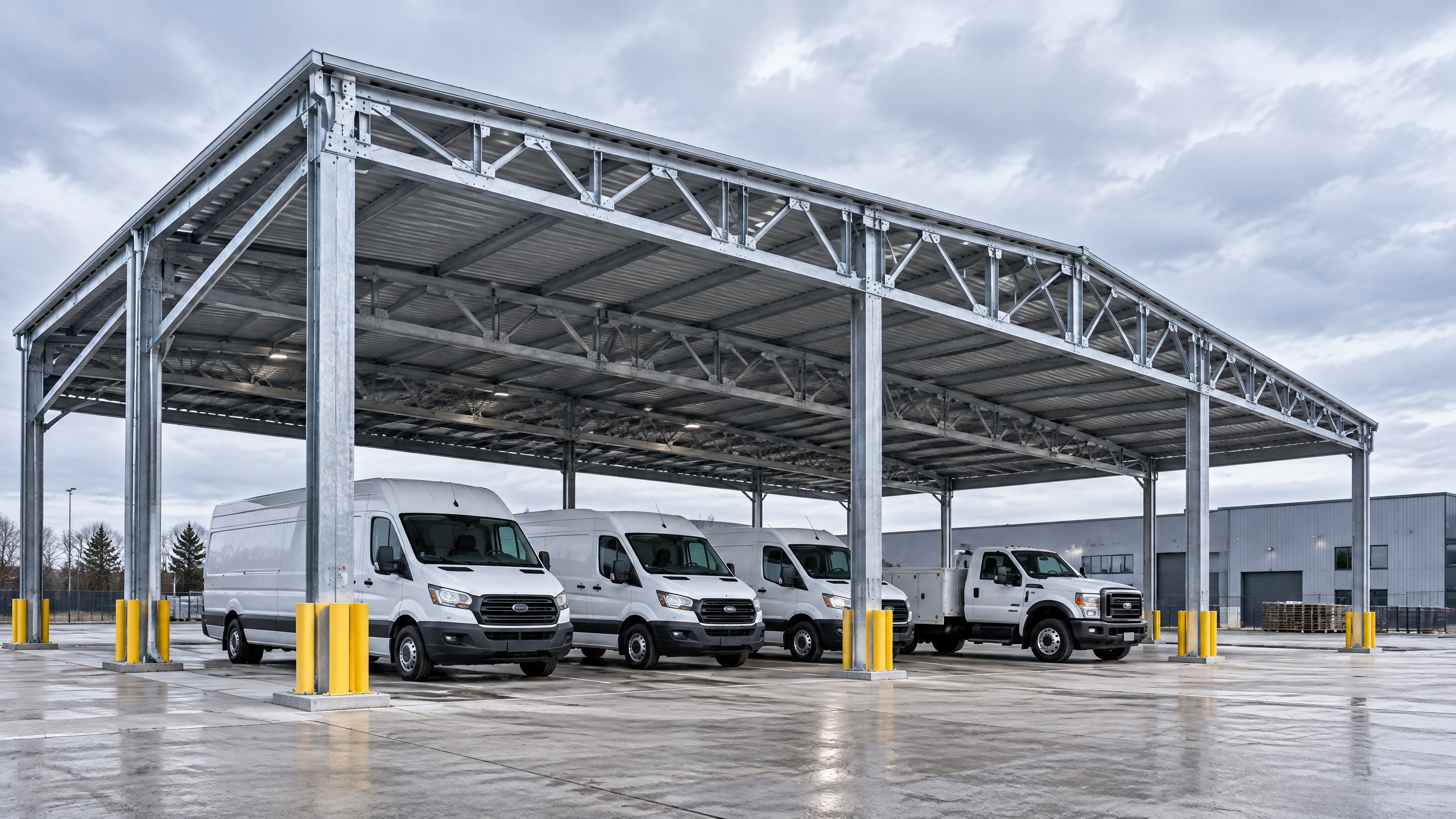
A clear specification for a delivery vehicle canopy steel structure starts with defining the vehicle fleet, operational patterns and the local site constraints, then using those inputs to drive structural, foundation and interface requirements. Begin by documenting vehicle dimensions, axle loads and daily manoeuvre patterns; combine this with geotechnical, drainage and flood risk data so structural canopy specification, vehicle clearance planning and commercial parking layout are consistent. Use performance-based procurement clauses that require material traceability, shop inspection records, connection design, lifting plans and factory acceptance evidence. Coordinate electrical, solar and lighting interfaces early so installation readiness and operational access coordination are part of the contract. Finally, structure the project into a project phasing plan that aligns procurement lead times and site works to avoid rework. Site-specific structural capacity, foundations, permits, electrical design, approvals, lead time, price, energy yield and warranty all require a documented project basis and confirmation from local qualified professionals, installers, utilities and authorities.
Buyer context and scope boundary
Who this guide is for
- Distributors, architects, contractors, developers, solar EPCs and fleet operators specifying industrial and commercial shelters for deliveries and logistics yards.
- Projects focused on covered loading/unloading, courtyards, fleet parking and combined solar carports where the primary structural subject is a delivery vehicle canopy steel structure.
Scope boundary — what this guide covers and what it does not
- Covers: functional requirements, design inputs, procurement evidence, factory and site handover topics, and an actionable six-step buyer workflow for procurement and implementation in commercial/industrial applications.
- Does not replace: local structural design by licensed engineers, site surveys, permit applications, full electrical design for PV or chargers, or legal contract drafting.
Key outcomes you should achieve
- A performance-oriented specification that defines: required clearances, structural load cases, material and corrosion resistance, integration points for PV and services, QA deliverables, and acceptance tests that support procurement and manufacture.
Constraints commonly observed
- Limited headroom inside existing structures; adjacent operations requiring uninterrupted access; varying geotechnical conditions; floodplains and constrained lead times. These constraints should be captured in the initial project brief to inform the project phasing plan.
Core decision principle
Make the delivery vehicle canopy steel structure a systems decision, not a component purchase. The central trade-offs are:
- Structural capacity vs. economy: larger spans and higher clearances increase steel tonnage and foundation sizes but reduce operational interference with vehicles and allow integration of PV arrays.
- Specification rigor vs. procurement flexibility: prescriptive specifications (materials, processes) reduce supplier variability but can limit competitive bids; performance specifications (loads, life, maintenance intervals) encourage innovation but require robust acceptance testing.
- Offsite fabrication vs. on-site adaptation: more factory work improves quality control and installation readiness but requires reliable transport and lifting capacity on site.
Decision drivers to prioritise
- Operational continuity: ensure operational access coordination between construction activities and daily deliveries.
- Lifecycle cost: include coatings, expected maintenance cycles, and refurbishment access in lifecycle models.
- Future-proofing: design clearances and modular canopy spans to accommodate larger vehicles or added services (e.g., EV charging, solar arrays).
Use these drivers to set measurable acceptance criteria in tender documents: design life (years), bolt grade and coating, wind and snow load cases, permissible deflection under service load, and evidence deliverables (e.g., material traceability, shop test reports).
Planning inputs — what information you must collect before design
Successful specifications begin with accurate, documented inputs. The table below lists core inputs, typical sources and why each matters.
| Input | Typical source | Why it matters |
|---|---|---|
| Vehicle inventory (dimensions, axle loads, turning radii) | Fleet operator, logistics plan | Defines required clearances, load cases and surfacing demands |
| Operational patterns (peak arrivals, shift changes) | Operations manager | Drives layout, phasing and temporary access needs |
| Commercial parking layout | Site plan, traffic engineer | Informs canopy footprint, circulation and egress |
| Geotechnical report | Geotech consultant | Determines foundation type, depths and anchorage |
| Flood and drainage risk | Local authority mapping, FEMA [2] | Affects foundation depth, elevation of decking and corrosion measures |
| Site survey & utilities plan | Land surveyor, utility providers | Prevents clashes with underground services during foundation works |
| Local codes and permits | Building authority, planning office | Sets mandatory safety, fire and structural compliance requirements |
| Environmental & corrosivity class | Local environment study | Selects coatings and material thicknesses |
| Power and PV integration requirements | Electrical engineer, solar EPC | Defines mounting loads and electrical penetrations |
| Accessibility requirements | Design team, guidance such as U.S. Access Board [1] | Ensures accessible parking and pedestrian routes where relevant |
Vehicle clearance planning and commercial parking layout must be validated together to avoid later rework: clearance envelopes, dock heights, and turning templates (swept paths) are the starting point for column positions and span lengths. For accessible parking and pedestrian ingress adjacent to loading areas, consult applicable guidance (for example, accessible parking guidance) to confirm aisle widths and pedestrian ramps [1].
Note on flood-prone sites: reference FEMA flood maps where relevant and incorporate flood elevations into foundation and equipment siting decisions [2].
Technical specification and interfaces
This section turns the planning inputs into technical requirements for the delivery vehicle canopy steel structure. Use a performance-first approach with prescriptive detail where necessary to control risk.
Structural design and loads
- Design basis should be documented: applicable local design codes (national/regional), wind, snow, seismic and live loads along with an explicitly stated design life (e.g., 25–50 years) and target performance.
- Load combinations and limit states must reflect service loads (vehicle impact load cases, maintenance loads, snow accumulation) and construction loads (temporary crane and assembly loads).
- Account for concentrated loads from mounted equipment (EV chargers, transformers, PV inverter cabinets) where applicable.
Material and fabrication
- Primary structure: specify steel grade (e.g., S355 or local equivalent) or performance criteria; require mill test reports (MTRs) for critical members.
- Connections: define bolt grades and tolerances (e.g., property class), welding procedures (WPS) and acceptance criteria (visual, NDT where required).
- Protective coatings: define corrosivity class and coating system (e.g., hot-dip galvanising + paint) with specified expected maintenance intervals. For coastal or high-corrosion sites, use higher protection classes and detail sacrificial elements.
- Tolerances: erecting tolerances, alignment allowances and anchor bolt positional tolerances should be included.
Foundations and groundworks
- Foundation type should be tied to geotechnical recommendations. Options include shallow pad foundations, combined footings, piled foundations or screw anchors depending on bearing capacity and groundwater.
- Include drainage and uplift mitigation for uplift/buoyancy in flood-prone sites.
- Service penetrations and ducts must be coordinated and grouted to the structural base plate detail.
Solar and electrical interfaces
- If the canopy carries PV (commonly in commercial and industrial applications), specify additional dead loads, point loads, cable routes and access hatch locations.
- Define interface points for inverter/comms cabinets and ensure space for ventilation and maintenance access.
- Require electrical contractor design interfaces during tender stage and define who supplies cable trays, conduits and earthing connections.
Roofing, drainage and snow shedding
- Define roof profile, maximum ponding allowance, and drainage downpipe locations.
- For flat or low-slope canopies, state ponding limits and clear access for cleaning. Snow-shedding can be significant for PV arrays; ensure the structural design accounts for asymmetric snow loads.
Safety and maintenance access
- Integrate walkways, service platforms and fall-arrest anchorage where PV or lighting requires regular maintenance.
- Define minimum vertical clearances, guardrail heights, and ladder access per local standards and safety regulations (installation safety should follow national rules such as OSHA during construction) [3].
Interfaces with site civils and traffic
- Column positions and bracing must be coordinated with the commercial parking layout to avoid obstructing circulation.
- Provide embedded plate and set-out drawings for column bases early to reduce site clashes with drainage or kerbs.
Structural canopy specification must be explicit about acceptance criteria for materials, workmanship and inspection regimes to avoid ambiguity at contract execution.
Procurement, factory evidence and quality assurance
Your procurement package should require verifiable evidence at each stage of production and delivery. Treat factory work as a controllable risk: greater off-site fabrication typically reduces installation time but requires robust documentation.
Minimum evidence and deliverables to require in contract
- Materials: MTRs, coating certificates and corrosion class confirmation.
- Fabrication: workshop inspection reports, welder qualifications, WPS records and dimensional control checklists.
- Assembly: manufacturer’s fit-up and alignment records, bolt torque records and packing lists.
- Structural calculations: signed and stamped structural analysis for critical members, connection design and foundation checks.
- BIM/CAD models: deliver as-built 3D models or coordinate files for clash detection.
- Factory Acceptance Tests (FAT): mechanical fit trials for bolted sub-assemblies; sample weld and coating checks.
- Transport and handling: documented lifting points, weight/centre-of-gravity data and dunnage requirements.
Decision table — Procurement pathways and evidence expectations
| Procurement pathway | Typical lead benefits | Evidence to require | When to choose |
|---|---|---|---|
| Turnkey supplier (design & supply) | Single point of responsibility; shorter co-ordination | Full design package, MTRs, FAT, erection drawings, O&M manual | Projects needing simplified procurement and single warranty |
| Supply-only (fabrication to client design) | Competitive price; client retains design control | Fabrication QC, MTRs, dimensional checks, weld records | When client/engineer provides complete design |
| Componentised supply with site assembly | Reduced crane hours; modular | Shop assembly checks, connection fit reports, transport plans | When site access is constrained |
| Design-Build with performance SLAs | Integrated design and installation | Design submissions, performance testing, commissioning reports | Complex sites or integrated PV + canopy systems |
Factory inspections and witness points
- Specify right-to-inspect clauses, third-party inspection (TPI) options and hold points (e.g., pre-coating, post-weld NDT, final painting).
- Arrange witness test sessions for critical welds or high-risk joints.
Quality assurance plan
- Require a QA plan showing manufacturing controls, non-conformance processes, and corrective action records.
- Include an inspection checklist aligned to the structural canopy specification and acceptance criteria.
Lead time management
- Require a manufacturing schedule with milestones tied to payment and progressive inspections.
- Plan for long-lead items: steel long-lead orders, custom sections, and special coatings; align these with the project phasing plan.
Mid-article CTA: For system-level solutions and modular options, review the Titan industrial and logistics system and our other configurations at all systems. For procurement templates and checklists see our sourcing guides. For direct procurement enquiries use /inquiry or contact info@carportiva.com.
Site installation, operations and installation readiness
Preparation and logistics
- Installation readiness starts with detailed delivery charts that record module weights, dimensions, required clearances and crane picks.
- Confirm access routes, road permits and temporary works (traffic management, pedestrian protection). Plan deliveries during off-peak operational hours where possible.
- Verify crane capacity with both the supplier and the installer; include contingency for sequential lifts and rated wind speeds for lifts.
Erection sequence and temporary works
- Sequence erection to maintain operational access and to minimise rework: install foundations, then columns, then primary beams, then roof modules.
- Use temporary bracing until full structural continuity is achieved. Ensure temporary bracing is specified and removed per engineer instructions.
Site testing and commissioning
- Structural checks: alignment, plumb, bolt torque checks and anchorage verification.
- Interface checks: roof sheetness, drainage tests, electrical conduits continuity and earthing. If PV is present, PV system commissioning and MCS/IEC-compliant tests by qualified electrical contractor must be completed separately.
- Handover deliverables: as-built drawings, certificates (MTRs, coatings), operation and maintenance manuals, and warranties.
Operational access coordination must be an explicit workstream during installation to minimise service disruptions. Allocate a site liaison and include emergency access corridors for deliveries during construction.
Maintenance and lifecycle considerations
- Schedule routine inspections for corrosion, bolt tension and drainage at defined intervals.
- Consider replaceable sacrificial elements (e.g., sacrificial columns, replaceable capping) in high-impact areas.
- Include provisions for PV cleaning and snow removal access if PV is installed.
Implementation risks and mitigation
Implementation of a delivery vehicle canopy steel structure entails multiple risks. Below are common risks with mitigations framed for contractual allocation.
Risk: Incomplete or inaccurate site surveys
- Mitigation: Require up-to-date site surveys and utility scans as a pre-condition for bid; include contingency pricing for discovered conditions.
Risk: Underground utilities or obstructions impacting foundations
- Mitigation: Early utility coordination, trial pits and geotechnical boreholes; specify contract change process and provisional sums.
Risk: Permitting delays
- Mitigation: Engage permitting authorities early; prepare application packages with clear drawings and calculations.
Risk: Supply chain delays for specialty steel or coatings
- Mitigation: Early procurement of long-lead items; specify substitute materials and alternative coatings pre-approved in contract.
Risk: Vehicle interference with column layout after installation
- Mitigation: Validate commercial parking layout and vehicle clearance planning during design freeze using swept path analysis and a mock-up if needed.
Risk: Site safety incidents during lifts and erection
- Mitigation: Enforce compliance with national construction safety regulations (e.g., OSHA for construction safety practices during erection) [3]; require site safety plans and method statements.
Risk: Flood or extreme weather events causing damage to foundations or equipment
- Mitigation: Integrate flood risk in foundation design (FEMA mapping where relevant) and elevate sensitive equipment; include insurance and natural hazard contingency clauses [2].
Risk allocation recommendations
- Design liability: supplier accepts responsibility for fabricated components to meet drawings/spec; engineer retains responsibility for site-specific foundation design.
- Unknown conditions: allocate to client with defined change control and cost/time buffers.
- Delays: define liquidated damages for late completion and extended time allowances for force majeure; ensure clarity on lead time dependencies.
Decision table — Foundation selection by ground condition
| Ground condition | Foundation option | Pros | Cons / when not suitable |
|---|---|---|---|
| High bearing capacity, no groundwater | Shallow pad/combined footings | Cost-effective, quick to construct | Not suitable if deep frost or high uplift expected |
| Low bearing, compressible soils | Piled foundations | Low settlement, high load capacity | Higher cost, longer programme |
| High groundwater or poor soils | Screw piles or driven piles | Fast installation, limited excavation | May be limited by obstructions; check for vibrations |
| Fill or contaminated ground | Deep piling with treatment | Avoids settlement and contamination spread | Requires specialist contractors and testing |
| Shallow rock | Rock anchors or drilled footings | Secure anchorage with minimal settlement | Requires rock coring and specialised process |
Named six-step buyer workflow
This is a practical, named workflow designed to be used as an actionable checklist for buyers procuring a delivery vehicle canopy steel structure in commercial settings.
1) Define operational brief and KPIs
- Actions: Document fleet types, daily throughput, required clearances, desired canopy functions (cover, PV-ready, EV charging), expected design life and maintenance expectations.
- Deliverables: Operational brief, KPI list, initial budget range.
2) Site baseline and constraints capture
- Actions: Commission a survey, geotechnical investigation, utility scan, site photos, and collect local planning/permitting requirements.
- Deliverables: Site survey, geotechnical report, underground utility map, site risk register.
3) Concept design and commercial parking layout
- Actions: Prepare layout options that integrate column grid, vehicle circulation (swept-path), pedestrian routes and accessible parking. Validate vehicle clearance planning and emergency vehicle access.
- Deliverables: Preferred layout, preliminary structural grid, massing sketches, concept-level cost estimate.
4) Detailed design and tender package
- Actions: Produce detailed structural drawings, foundations, services interfaces, specification (structural canopy specification), QA requirements and acceptance criteria. Issue an RFT/RFP with performance and evidence requirements.
- Deliverables: Issue-quality tender package, evaluation matrix and expected delivery programme.
5) Procurement, factory verification and logistics planning
- Actions: Award contract, schedule factory inspections, agree FAT scope, and prepare transport/installation logistics and traffic management.
- Deliverables: Manufacturing schedule, FAT reports, logistics plan, lifting plan, insurance and warranties.
6) Installation, commissioning and handover
- Actions: Supervise erection, perform site inspections, test services, commission PV/lighting/EV systems (if applicable), and compile as-built documentation and maintenance plan.
- Deliverables: Signed acceptance certificate, as-built drawings/BIM, O&M manual, warranty certificate(s).
Each step should have clear acceptance criteria and a responsible party. Use stage gates with hold points to review evidence before proceeding to the next phase.
FAQ
Q: How high should a delivery vehicle canopy be for a standard delivery truck? A: There is no universal height. Specify clearance using your fleet tallest vehicle plus operational allowance for lifting tail lifts, articulated movement and any lighting or signage under the canopy. Validate with swept-path and vertical clearance templates. Also confirm local code minimums for pedestrian routes and accessible parking [1].
Q: Who designs the foundations for the canopy? A: The foundation design is site-specific and should be produced by a licensed structural/geotechnical engineer based on a geotechnical investigation. The supplier can provide foundation drawings for review, but the client’s engineer should stamp and approve them where required.
Q: Can the canopy support solar panels? A: Yes, canopies can be designed to support PV arrays, but that requires additional structural load allowances, electrical routing, inverter locations and maintenance access. PV structural and electrical design must be coordinated between the canopy designer and the solar EPC.
Q: What documentation should I expect at handover? A: At minimum: as-built drawings, material certificates (MTRs), welding and NDT reports (if applicable), coating certificates, FAT reports, installation completion checks, and an O&M manual. Warranty terms should be documented separately.
Q: Are there accessibility considerations near loading areas? A: Yes. Accessible parking, ramps and pedestrian paths must meet local accessibility guidance. For example, guidance on accessible parking layout and dimensions is available which should be consulted during layout planning [1].
Q: What safety standards apply during construction? A: Construction safety is subject to national/regional regulations and on-site safety plans; in many jurisdictions OSHA provides construction standards that should inform method statements and site procedures for lifts and fall protection [3].
Q: Can weather or flood risk affect canopy choice? A: Yes. Flood-prone sites require elevated equipment and special anchorage; wind or snow-prone regions affect load cases. Use local flood maps and meteorological data to inform design [2].
Q: How long does procurement typically take? A: Procurement varies widely by complexity, scale and factory lead times. Include explicit lead-time allowances in the project phasing plan and request manufacturing schedules from bidders. Lead time depends on steel availability, bespoke components and coatings.
Conclusion
Specifying a delivery vehicle canopy steel structure for a commercial carport project is a multidisciplinary task. The primary requirement is to translate operational needs—vehicle dimensions, flow, and maintenance—into measurable structural requirements and procurement evidence that reduce ambiguity. Prioritise: robust site surveys, clear interface definitions (electrical, PV, drainage), factory QA and staged inspections. Use a performance-led specification combined with explicit documentary requirements (MTRs, FAT, as-built BIM) to balance supplier flexibility with risk control.
Remember: site-specific structural capacity, foundations, permits, electrical design, approvals, lead time, price, energy yield and warranty require a documented project basis and relevant local qualified professionals, installers, utilities and authorities.
For system options and modular logistics solutions see the Titan industrial and logistics system at /products/titan. For procurement templates and sourcing guidance visit sourcing guides. If you are ready to proceed or want a project review, contact us via /inquiry or email info@carportiva.com.
References
- U.S. Access Board parking guidance: https://www.access-board.gov/ada/guides/chapter-5-parking/
- FEMA flood maps: https://www.fema.gov/flood-maps
- OSHA construction standards: https://www.osha.gov/laws-regs/regulations/standardnumber/1926
- Federal Highway Administration: https://highways.dot.gov/
Keep the project brief connected.
Bring the actual project brief to the engineering table.
Share your location, layout, target application and available technical inputs. Carportiva can help identify the relevant product-interface information before a project-specific commercial discussion.
Request a project discussion