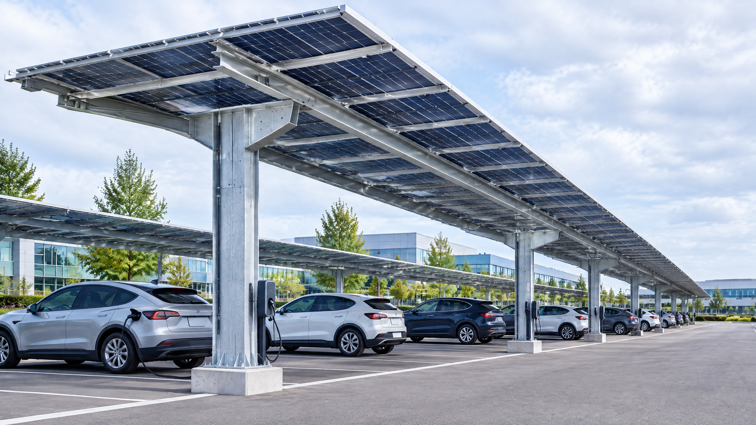
# How Should Inverter and Electrical Equipment Locations Be Planned for a Solar Carport?
A solar carport inverter layout should be planned as a coordinated equipment-and-access system. Start with the electrical single-line concept and utility point of interconnection; then reserve protected, serviceable locations for inverters, disconnects, switchgear, meters, communications hardware, and any transformer or energy-storage interfaces.
For B2B buyers: Can required parties safely reach, inspect, isolate, meter, maintain, and replace equipment without compromising parking operations or the approved electrical design?
In the United States, OSHA requires sufficient access and working space around applicable electrical equipment and prohibits using the required working space for storage.[1] Utility requirements can also dictate how meters, disconnects, and other service equipment are grouped or positioned. One published utility guide, for example, groups the directory plaque, service disconnect, billing meter, PV meter, PV AC disconnect, and energy-storage disconnect where practical; it also illustrates why a site-specific utility review must happen before equipment is fixed in the field.[2]
This guide helps owners, developers, architects, general contractors, and procurement teams frame the layout decision. It does not replace electrical, structural, civil, fire-protection, accessibility, or utility design. Local qualified engineers, licensed installers, utility providers, and authorities having jurisdiction (AHJs) determine final project decisions, applicable codes, equipment ratings, clearances, settings, permits, and approvals.
Define the electrical architecture before reserving physical space
The first layout decision is electrical, not architectural. A carport may have one or more PV blocks, string or central inverter topology, AC collection equipment, a transformer, a point of common coupling, production metering, a service upgrade, EV charging, battery storage, controls, and communications. Their locations cannot be optimized independently. A short DC run may create a poor AC collection route; a tidy-looking meter position may conflict with the serving utility’s preferred arrangement; a convenient column location may sit in a vehicle impact zone.
Ask the engineer of record for an equipment schedule and preliminary single-line diagram identifying each device’s function, access face, mounting envelope, manufacturer requirements, conduit entries, communications, and responsible accessor. Do not assume equipment from one manufacturer has the same clearance, environmental, or mounting requirements as another. IEEE 1547 covers DER interconnection and interoperability subjects including performance, testing, safety, maintenance, and commissioning.[3] The location should enable the final utility-approved controls, metering, protection, disconnecting means, and tests.
Start with a location hierarchy, not a single “best” spot
A useful hierarchy tests several zones in order:
- A dedicated electrical yard or equipment pad near the service or point of interconnection, where site area and security permit.
- A protected wall or freestanding equipment screen beside, rather than within, active parking circulation.
- A purpose-designed carport equipment bay or end-of-canopy zone that is structurally suitable and physically protected.
- Column-mounted equipment only where manufacturer instructions, structural design, working-space rules, accessibility, emergency access, and vehicle protection are all resolved.
Build an equipment-location register
Procurement teams can request a location register early. This avoids a generic specification that lists devices without showing how they will coexist. The register should state the proposed zone and unresolved dependencies for every major component.
| Equipment or interface | Location question the buyer should ask | Coordination evidence to request | Typical decision owner |
|---|---|---|---|
| PV inverter or inverter group | Is the mounting or pad location protected, ventilated as specified, and reachable for service and replacement? | Manufacturer installation data; layout elevation; structural support detail | Electrical engineer and installer |
| DC combiner or transition equipment, if used | Does the route reduce exposed DC pathway complexity without obstructing access? | String/raceway plan; labeling concept | Electrical engineer |
| AC disconnect and protection | Can authorized personnel reach and identify it without crossing a parking hazard or blocked path? | One-line diagram; site plan; lockout/isolation narrative | Electrical engineer, utility, AHJ |
| Revenue or production meter | Does the exact position meet the serving utility’s equipment grouping and access rules? | Utility correspondence; meter layout or variance, if applicable | Utility and electrical engineer |
| Transformer or service equipment, if required | Are pad, working space, civil levels, and vehicular protection coordinated? | Utility civil/electrical requirements; grading plan | Utility, civil and electrical engineers |
| Monitoring gateway and communications | Is there a protected route, network boundary, and maintainable power/communications interface? | Communications diagram; cybersecurity responsibility matrix | Owner IT and installer |
| EV charging or storage interface, if included | Are load management, isolation, emergency procedures, and future service boundaries documented? | Coordinated one-line; operating sequence; equipment schedule | Electrical engineer and owner |
Select an equipment zone that protects access, service, and parking operations
A solar carport is a working parking facility. Vehicle turning, accessible spaces, passenger routes, storage, delivery activity, and maintenance vehicles can turn apparently open space into a poor equipment location. Distinguish electrical working space, pedestrian circulation, vehicle clear zones, emergency approach paths, and construction staging on the site plan.
For applicable equipment at 600 volts nominal or less to ground, OSHA requires sufficient access and working space. Its cited rule describes depth by condition and voltage, a front working width at least equal to equipment width or 30 inches, and door/panel opening of at least 90 degrees where energized servicing is contemplated.[1] It is not a substitute for locally adopted electrical code, manufacturer instructions, or utility standards; do not treat the area as parking, landscaping, or storage.
Compare physical-location options against the whole project
| Candidate zone | Strengths | Planning risks to resolve | Buyer decision test |
|---|---|---|---|
| Dedicated pad or electrical yard | Clear separation from parked vehicles; easier replacement access; room for grouped equipment | Land take, fencing, drainage, utility route, visual treatment, service access | Can the pad remain accessible and clear throughout operations and after storms? |
| Equipment screen beside parking | Can preserve short AC runs while separating equipment from bays | Screen may conceal access constraints, affect ventilation, or collect debris; route to service still matters | Is the screen designed around manufacturer clearances and door swing, not merely appearance? |
| End-of-canopy equipment bay | May align with carport structure and reduce visible clutter | Vehicle impact, structural support, shade/thermal environment, pedestrian crossover, drainage from canopy | Has a structural and vehicle-protection detail been issued, with the access face outside the traffic envelope? |
| Column-mounted inverter | Uses existing vertical structure and can shorten DC cabling | Restricted working space, collision exposure, access-route obstruction, inadequate replacement handling | Can a technician safely access the unit with parking operations controlled and no accessible route reduced? |
| Building/service-wall location | May simplify interconnection and monitoring connections | Long route to array, penetrations, building coordination, fire/life-safety interfaces | Has the building electrical room or exterior service zone been reviewed for capacity, access, and routing? |
Treat accessibility and vehicle protection as drawing requirements
Do not place equipment, bollards, enclosures, or open doors in a way that narrows an accessible route. The U.S. Access Board explains that accessible exterior routes connect accessible parking and site arrival points to facilities, and continuous clear width generally cannot be reduced by protruding objects.[4] Show affected routes on the plan.
Where cars can reach equipment, coordinate impact protection with civil, structural, and electrical packages. Bollards can obstruct service access, door swing, accessible circulation, and replacement handling. Establish the vehicle envelope, protection strategy, and technician approach together; the appropriate curb, setback, pad, barrier, or revised zone is site-specific.
Mid-article CTA — Need a procurement-ready equipment coordination brief? Share the carport footprint, preliminary one-line, parking plan, and utility status through Carportiva’s inquiry form or email info@carportiva.com. The final layout remains subject to local engineering, installer, utility, and AHJ review.
Coordinate environmental exposure, drainage, and enclosure conditions
Carport equipment may see solar and pavement heat, wind-driven rain, canopy runoff, dust, de-icing materials, debris, and seasonal inundation. Plan from site conditions and manufacturer instructions, not an assumption that any outdoor enclosure solves every exposure.
DOE guidance for elevated PV systems such as canopies calls for assessing mapped flood risk and local stormwater inundation; a site outside a mapped floodplain can still experience standing water. It says submerged inverters, switchgear, meters, and other hardware need replacement.[5]
Put water management on the same plan as electrical equipment
Request a civil/electrical overlay showing grades, inlets, swales, downspouts, overflow paths, pad elevations, conduit routes, and equipment bases. DOE identifies raising equipment and preventing water flow into conduits as mitigation measures.[5] The project engineer determines applicability, elevation, sealing, enclosure, and floodplain obligations.
Avoid drainage low points and discharge locations. For weather-exposed enclosures, require evidence that orientation, mounting, cable entries, and sun exposure follow manufacturer instructions, and assign installation verification before energization.
Manage heat, dust, and replacement access as an operational system
Thermal and ventilation requirements are manufacturer-specific. Request the installation manual, operating environment, spacing/airflow, mounting limitations, and direct-sun or screen constraints; never use a generic clearance for every model. NREL links design to O&M through equipment access, clearance, elevated pads where needed, and maintainable equipment.[6] Show how a technician reaches, opens, and replaces components.
Fix the utility, metering, protection, and emergency interfaces early
The utility interface often drives equipment location, particularly when service is remote, equipment changes are needed, or transformer, CT metering, EV charging, or storage is involved. Treat interconnection as a design gate.
Austin Energy’s published guide illustrates the types of utility-controlled details: grouping, metering clearance, equipment suitability, and accessible, lockable AC disconnects in its cited configuration.[2] Those rules are not universal. Obtain requirements from the serving utility and reflect them in issued drawings.
Create a coordination matrix before equipment procurement
| Interface | Question to close before release | Evidence of closure | Consequence if left open |
|---|---|---|---|
| Point of interconnection | Where exactly does PV connect, and what service modifications are required? | Utility-reviewed interconnection concept or documented direction | Rework of feeders, switchgear, trenching, or carport equipment zones |
| Metering | What meter type, grouping, access, and mounting configuration does the utility require? | Utility layout acceptance or written response | Meter relocation, inaccessible equipment, or delayed service work |
| Protection and controls | What inverter functions, protective devices, settings process, and witness testing apply? | Approved one-line and utility/engineer coordination record | Commissioning delay or nonconforming settings |
| Emergency isolation | Which disconnects or shutdown devices must be accessible and how are they identified? | Fire/AHJ review comments; labeling schedule | Confusing emergency response or late labeling changes |
| Communications | Who provides network path, cybersecurity review, and ownership of monitoring data? | Network diagram; responsibility matrix | No commissioning connectivity or unmanaged access |
| Civil interface | Where are pads, trenches, pull boxes, and restoration areas? | Civil/electrical overlay and utility civil requirements | Conflicts with foundations, drainage, or traffic routes |
Design for emergency recognition, not just normal operation
Emergency responders and facility staff need to recognize the system and its isolation points. DOE notes that response involves identifying the system, shutting it down, managing hazards, and confirming safety.[7]
Fire/AHJ requirements can affect the plan. LAFD, for example, asks that plan review show array locations, disconnects, signage, and access pathways; its markings help responders identify energized lines and isolate the system.[8] This is a local example, not a nationwide rule. Ask what the local authority needs and where responders approach.
Specify a permanent labeling schedule. OSHA also requires durable, legible marking of certain disconnecting means.[1] Responsible professionals and authorities set final language, placement, material, and compliance.
Specify evidence from factory submittal through shipment and installation
A sound solar carport inverter layout can fail during procurement if the actual delivered enclosure, mounting arrangement, cable-entry side, door swing, or dimensions differ from the assumptions used on the civil and structural drawings. Buyers should make physical coordination a submittal requirement and tie it to the approved layout.
Request a coordinated equipment data package before release for fabrication or shipment. At minimum, it should include manufacturer cut sheets; model identifiers; dimensions and weights; required clearances and mounting orientation; environmental limitations; installation instructions; connection and conduit-entry information; heat-rejection/ventilation information; equipment listing or certification evidence relevant to the jurisdiction; and a marked-up plan/elevation showing the exact proposed location. UL Solutions explains that its PV inverter and converter testing and certification services cover a range of standards and that test scope partly depends on whether a product is standalone or intended for local utility interconnection.[9] The buyer should request documentation appropriate to the location and project—not make an unsupported claim that a device is accepted by a particular authority.
Use hold points to protect layout integrity
Include clear hold points in the procurement and installation plan:
- Design hold point: Issue the coordinated site plan, one-line, equipment schedule, and utility/AHJ comments status before equipment-zone fabrication is finalized.
- Submittal hold point: Confirm that proposed product data match the approved mounting, ventilation, access, and enclosure assumptions.
- Pre-shipment hold point: Check serial/model records, packing list, physical dimensions, accessories, brackets, labels, and storage instructions against the approved schedule. Photograph condition where contract procedures require it.
- Pre-installation hold point: Verify field grades, foundations, embeds, vehicle-protection work, pathways, trench routes, communications readiness, and working-space boundaries before mounting equipment.
- Pre-energization hold point: Confirm labels, access, enclosure integrity, grounding/bonding work, diagrams, utility requirements, and commissioning readiness against the final drawings and responsible parties’ procedures.
The objective is traceability, not bureaucracy. NREL recommends system documentation including as-built drawings, specifications, site plans, photo records, safety information, single-line diagrams, installed-component cut sheets, operating manuals, and emergency procedures within an O&M plan.[6] These records help the owner maintain a layout that remains understandable after the construction team has left.
Require an installation-access plan, not only a layout drawing
A layout drawing shows intended final positions. An installation-access plan addresses how equipment gets there and how it will later be replaced. Require the installer to identify delivery route, laydown area, lifting or handling constraints, traffic control, protection of finished paving, temporary enclosure/storage needs, planned outages if any, and how access to the electrical working area will be preserved. This is especially important where an inverter is mounted within the carport structure, because a parked vehicle or a carport beam may limit handling more than a plan view suggests.
Do not allow shipment timing to force a location decision. If utility confirmation, manufacturer data, or a foundation detail remains open, record the risk and resolve it before irreversible civil work or equipment release. A staged shipment can be practical only when the responsible project team confirms storage, security, condition protection, and sequence.
Convert the layout into a buyer acceptance and O&M handover plan
The final solar carport inverter layout is only successful if operators can use it safely and understand its boundaries. Acceptance should verify the condition shown on the issued design and create an orderly handover package for the owner’s facilities, maintenance, security, and IT teams.
DOE’s PV O&M guidance recommends routine site monitoring, debris control around electrical equipment, proper information management of monitoring systems, and electrical inspection after inverter nuisance tripping rather than simply resetting the system.[10] This supports a buyer requirement for access instructions, alarm ownership, response procedures, and a record of configuration responsibility. It does not prescribe a universal maintenance interval; equipment manufacturer instructions and the owner’s O&M plan should govern the site.
At handover, inspect the whole journey a technician or responder will take: approach from the site entrance, reach the equipment zone, identify the equipment and disconnects, open necessary doors, maintain required work space, avoid traffic and pedestrian paths, and leave without crossing an obstruction. Compare the as-built condition with the approved plan and record deviations. A late-installed planter, parking sign, bicycle rack, utility cabinet, or storage practice can invalidate an otherwise correct layout.
The acceptance package should include a current one-line, equipment schedule, site/electrical plan, labeling schedule, installed product data, interconnection and commissioning records as applicable, monitoring handover instructions, emergency and normal operating procedures, approved field changes, and photographs of equipment faces and approach paths. Confirm who controls keys, access credentials, and network permissions. Responsibility clarity is often more valuable than a generic “turnover complete” certificate.
Buyer workflow: plan a solar carport inverter layout in 10 steps
- Collect site constraints. Assemble survey, parking circulation, accessible-route information, utility records, electrical service data, drainage/flood information, existing underground utilities, architectural constraints, and operating hours.
- Establish the electrical concept. Have the qualified electrical team prepare a preliminary one-line, equipment schedule, topology rationale, point-of-interconnection concept, and preliminary feeder/raceway routes.
- Map candidate equipment zones. Test a dedicated yard, screened wall, canopy-end bay, column option, and building/service location against service, safety, civil, and operational criteria.
- Overlay access boundaries. Draw equipment work areas, door swings, service approach, pedestrian routes, accessible paths, traffic envelopes, and emergency access on the plan.
- Start utility and AHJ coordination. Submit the early concept required by the serving utility and local permitting/fire authorities; record open requirements rather than assuming them.
- Coordinate civil and structural details. Resolve foundations, mounts, pads, equipment elevation, drainage, trenching, pull points, protective measures, and replacement handling.
- Issue a procurement-ready equipment register. Link each planned location to product data needs, exact model assumptions, required accessories, interfaces, and approving discipline.
- Review factory submittals before release. Check that dimensions, mass, door swing, conduit entries, environmental requirements, and mounting instructions match the approved arrangement.
- Use field hold points. Verify site conditions before installation, then inspect working space, labels, access, enclosure condition, and completed interfaces before energization.
- Accept the operational layout. Receive as-builts, commissioning/interconnection records as applicable, O&M material, photos, monitoring access, and named responsibilities for future maintenance.
Frequently asked questions about solar carport inverter layout
Can an inverter be mounted on a solar carport column?
It may be possible, but it is not automatically the best or acceptable solution. The responsible engineer and installer should verify the structural support, manufacturer mounting instructions, environmental exposure, service access, working space, conduit routing, vehicle impact risk, pedestrian/accessibility effects, and local utility/AHJ requirements. A column location should be rejected if it depends on using an active parking bay or circulation route as the service area.
Should inverters be placed close to the carport modules or close to the service equipment?
There is no universal answer. The preferred location follows the complete electrical architecture: DC and AC routing, voltage-drop and conductor design, inverter topology, utility interconnection, metering, protection, access, civil work, and manufacturer instructions. Ask the qualified electrical engineer to compare alternatives on the actual single-line and site plan rather than choosing on cable length alone.
How can buyers prevent equipment from being blocked after commissioning?
Make equipment access a facilities rule as well as a construction requirement. Mark and document the work area, include it in site drawings and turnover photographs, train facilities staff, and prohibit storage, temporary parking, landscaping, or furniture that intrudes on required access. Periodic inspections should check for new obstructions. OSHA’s cited requirements state that applicable working space may not be used for storage.[1]
Why involve the utility before the carport structure is finalized?
The utility may have requirements for the point of interconnection, service modifications, meter arrangement, disconnect access, transformer or pad location, protection, and testing. Those requirements may affect conduits, foundations, equipment grouping, carport placement, and schedule. Early coordination reduces the likelihood that physical works have to be altered after installation.
What evidence should be in the handover package?
Request current as-built plans and single-line diagrams, equipment data, manufacturer installation and O&M material, labeling record, commissioning and interconnection documentation as applicable, monitoring/access information, emergency procedures, field-change record, and photographs. NREL identifies these kinds of system documents as core O&M-plan content.[6] The project team should set the final package and acceptance criteria.
Conclusion: buy a coordinated access system, not just inverter hardware
A strong solar carport inverter layout is the outcome of early electrical, civil, structural, operational, utility, accessibility, and emergency-response coordination. It reserves a real equipment zone; protects working and pedestrian access; anticipates water, heat, and vehicle exposure; confirms utility and metering interfaces; and preserves documentation from factory submittal through commissioning and O&M handover.
For buyers, the most defensible procurement requirement is a coordinated package: preliminary and final one-lines, location register, site/electrical overlays, manufacturer data, utility/AHJ status, installation-access plan, hold-point records, and accurate as-builts. Require the project team to explain how equipment will be reached, isolated, serviced, and replaced in the finished parking environment. Local qualified engineers, installers, utility providers, and authorities having jurisdiction must make the final project decisions.
Ready to organize the sourcing and coordination inputs? Use Carportiva’s inquiry form or email info@carportiva.com with the available site plan and electrical concept.
References
Bring the actual project brief to the engineering table.
Share your location, layout, target application and available technical inputs. Carportiva can help identify the relevant product-interface information before a project-specific commercial discussion.
Request a project discussion