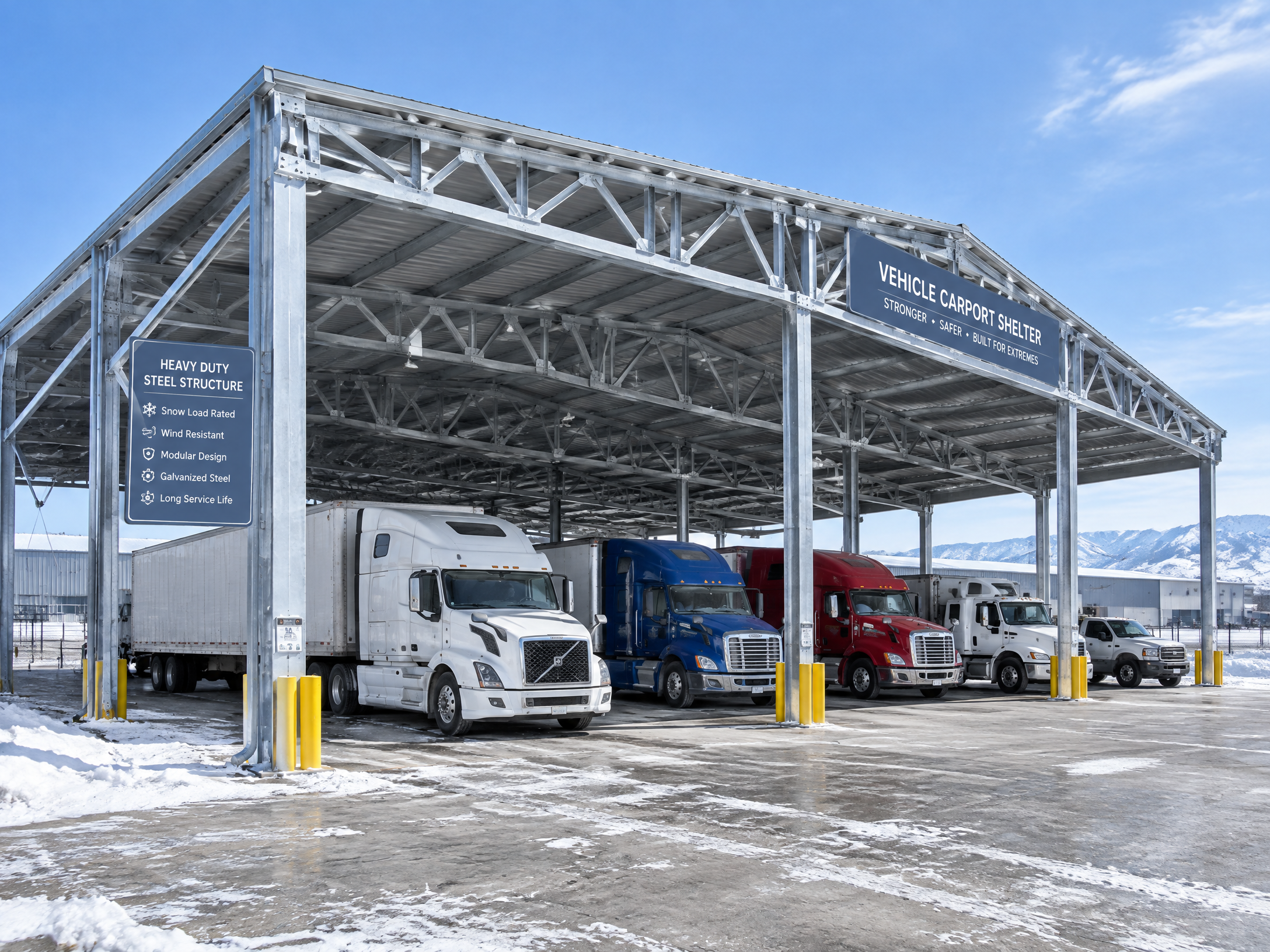
# How Should a Carport Project Address Vehicle Impact Protection?
A carport project should address carport vehicle impact protection as a site-specific risk-control decision, not as an accessory added after the steel package is selected. Start by mapping where vehicles can travel, turn, reverse, queue, park, load, charge, or lose control. Then decide which structural legs, electrical equipment, pedestrians, accessible routes, buildings, and utilities could be exposed. The design team can use that map to reduce conflict through layout first, then add physical protection where exposure remains.
The procurement brief should require a coordinated basis of design: the intended vehicle types and operations, traffic directions, parking geometry, protected assets, applicable local requirements, ground and utility constraints, barrier performance evidence where a barrier is proposed, and installation hold points. This creates a traceable path from site risk to equipment selection and field verification. It also prevents a common mistake: treating a wheel stop, a visual line, a decorative post, and a tested vehicle restraint as interchangeable.
A manufacturer can provide product information, drawings, and fabrication records, but those items do not replace project engineering or authority review. Local qualified engineers, installers, utility providers, and authorities determine final project decisions, including whether impact protection is needed, what type is appropriate, how it is founded, and what approvals or inspections apply.
Buyer context and scope boundary
This guide is for B2B buyers of parking canopies, solar carports, EV-charging canopies, fleet shelters, and covered circulation areas. It addresses low-speed parking as well as exposed edges near drive aisles, delivery activity, streets, service yards, or fleet movements.
Impact protection manages vehicle contact with a defined object or area; it does not replace the primary structural, pavement, drainage, traffic, emergency-access, electrical, fire, or accessibility design. A canopy column may not be intended for impact, while a barrier can transfer force into its foundation and surrounding pavement. Coordinate the systems rather than assuming either protects the other.
Roadside terminology needs careful translation. FHWA says safety hardware can reduce potential crash severity and that crash testing evaluates crashworthiness, but it also cautions that laboratory scenarios cannot cover every real-world condition. [1] A parking carport is not automatically a highway application. Do not describe a product as “MASH approved” for a carport or treat an FHWA eligibility letter as project approval; FHWA says Federal-aid reimbursement eligibility is not approval, certification, or endorsement for a particular use. [1]
Use evidence proportionate to the exposure and let the project engineer judge its applicability. FHWA describes AASHTO’s Manual for Assessing Safety Hardware (MASH) as uniform crash-test guidance for highway safety features. [2] The test configuration and site condition still need comparison.
What exposure should the buyer identify before selecting a barrier?
Start with: “What credible vehicle path could reach what asset, with what consequence?” Use a site walk, parking plan, aerial view, traffic observation, and facilities input. Build the risk register around movements, not product categories.
Map approaches to canopy legs, electrical equipment, EVSE, doors, accessible parking, transformers, and façades. Mark forward and reverse travel, turns, queues, shortcuts, grades, and delivery routes. Note wet pavement, poor sightlines, opposing circulation, narrow turns, confusing striping, and direct approach paths.
Record the vehicle population: passenger cars, delivery vans, shuttles, refuse or maintenance trucks, forklifts, trailers, and any exclusions. Frequency and consequence both matter. State fleet and operating assumptions rather than borrowing an impact criterion from another site.
Separate people, asset, and structural protection. A device that limits contact with a charger may not protect a pedestrian route, while posts near a canopy leg may create an obstruction. State the intended outcome.
| Exposure question | Evidence to collect | Procurement consequence |
|---|---|---|
| Which vehicles can enter the area? | Fleet list, visitor mix, delivery schedule, photos of actual operations | Set the design vehicle and state exclusions explicitly. |
| Where can a vehicle approach a protected item? | Dimensioned plan, turning paths, grades, wheel positions, reversing routes | Locate protection for the credible approach path rather than placing it by appearance. |
| What is being protected? | Asset list for columns, EVSE, electrical gear, doors, pedestrians, accessible routes, utilities | Define the required outcome for each asset or area. |
| What site features change the risk? | Drainage, slopes, curbs, intersections, sightlines, pavement condition, street interface | Consider layout and traffic changes before specifying a physical barrier. |
| Who controls operations? | Parking policy, loading plan, delivery instructions, maintenance procedures | Align signs, markings, access control, and barrier placement with actual operations. |
A useful risk statement is specific without pretending to be a calculation: “Reverse-moving delivery vehicles may pass a canopy end column during servicing; maintain a protected pedestrian route and evaluate vehicle restraint at that edge.” This is more usable than “provide bollards as required.”
Decision gate: Do not release a carport layout for fabrication until the buyer has identified the vehicle routes and protected assets on a coordinated site plan. A vendor quote based only on bay count, span, and finish cannot resolve impact exposure responsibly.
Which risk-reduction hierarchy should shape the carport layout?
Use this hierarchy: eliminate the conflict, reduce the chance of reaching it, guide the driver, physically restrain the vehicle where needed, and manage residual risk. Layers normally perform better than a single item.
Eliminate through geometry. Keep columns outside vehicle envelopes, create stand-off, avoid legs at exposed bay ends or sharp turns, and use circulation that does not aim at a column, enclosure, or entrance. A change to bay alignment, drive direction, or island location can remove recurring exposure.
Reduce ambiguity. One-way flow, obvious turning space, delivery controls, and separate service access can help. Confirm the owner can maintain these measures. Markings or a posted speed do not correct an impossible turn.
Guide the driver. Markings, wayfinding, delineation, lighting, mirrors, and clearance signs can improve recognition. OSHA’s forklift guidance is not a carport standard, but it recommends separating vehicles and pedestrians where possible and addressing blind corners and obstructed vision. [5] Visual measures do not replace physical separation where consequences are serious.
Add separation or restraint. Raised islands, curbing, rails, barriers, bollards, wheel stops, or a designed combination can serve different roles. A wheel stop sets a normal parked position; a curb or island channels movement. A barrier or bollard intended to resist impact needs a documented design basis, installation detail, and foundation interface.
Manage residual risk. Inspect and replace damaged components, review impacts, and control the area after a strike. A standing barrier, cracked foundation, bent column, or moved electrical equipment may no longer perform as intended.
| Control type | Best use in a carport project | What it does not prove on its own |
|---|---|---|
| Repositioned columns, altered bays, or changed circulation | Removing an approach path or increasing stand-off | That all future vehicle types can use the revised geometry safely. |
| Signs, striping, lighting, and delineation | Helping drivers understand circulation and boundaries | Resistance to vehicle contact or continuing compliance after markings fade. |
| Wheel stops | Controlling normal parked wheel position where compatible with the layout | Impact resistance for a moving or misdirected vehicle. |
| Curbs and landscaped or paved islands | Channelizing movement and creating stand-off | A defined vehicle-restraint performance level. |
| Bollards, rails, or proprietary vehicle barriers | Resisting a stated exposure when designed and installed for that purpose | Suitability without matching evidence, foundation design, and site review. |
| Pedestrian railings or fences | Discouraging crossing and guiding people to a route | Vehicle-impact resistance unless specifically engineered and documented. |
Use the hierarchy to price carport, civil, signage, and protection scopes together. Require bidders to identify inclusions, exclusions, and decisions needed before fabrication.
Mid-article CTA: Need a sourcing brief that separates canopy scope, civil work, electrical interfaces, and impact-protection evidence? Send the site plan and procurement questions to info@carportiva.com or use Carportiva’s inquiry form.
How should barriers, bollards, and foundations be specified without overclaiming performance?
A defensible specification starts with an owner-approved performance brief prepared or accepted by the qualified engineer. Identify the exposed asset, vehicle assumptions, approach direction, operating condition, desired outcome, needed clearance behind the protection, ground conditions, and utilities. Say whether the goal is guidance, asset protection, pedestrian separation, or containment.
For proprietary systems, request the exact configuration, product identification, relevant test report or summary, stated conditions, installation instructions, limitations, anchor or embedment information, foundation requirements, repair procedure, and inspection guidance. Evidence only applies when the installed condition matches it; a report for one height, spacing, substrate, anchor system, approach, or edge distance may not support another.
For cast-in-place or custom protection, request sealed calculations and details where required. Coordinate reinforcement, bases, embedment, slab joints, drainage, pavement, and corrosion environment. Do not ask a carport fabricator to assure impact resistance unless a qualified engineer has defined the action and designed the load path.
Show the protected zone, any movement allowance, and maintenance clearance. A barrier placed too close can reach the asset after impact or block service; excess stand-off can harm parking usability.
Roadside evidence must be described carefully. MASH is a crash-test framework for highway safety features, not a universal quality label. [2] FHWA also emphasizes that controlled testing cannot account for all field variables. [1] Where such evidence is relevant, the buyer should ask the engineer to compare the test setup and result to the site’s defined exposure. Where it is not relevant, the engineer may select another documented basis that fits the jurisdiction and project. Never substitute a marketing term, a photograph, or a general statement of “crash rated” for the actual evidence.
The same discipline applies to anchors. Surface-mounted systems may depend on a slab condition that is not present; cast-in-place work may conflict with utilities or drainage. Review the barrier, pavement, and canopy foundation packages together before release.
How can a project protect people while preserving parking access and accessibility?
A safety feature that narrows an accessible route or sits in an access aisle introduces another problem. Accessibility should be checked on the composite layout: carport columns, bollards, signs, charger pedestals, wheel stops, curbs, drainage inlets, railings, and landscaping—not just on a clean architectural plan.
The U.S. Access Board explains that accessible parking spaces and access aisles have requirements for size, surface, marking, vertical clearance, identification, and connecting accessible routes. Its guidance states that bollards, signs, columns, and other elements cannot sit in the access aisle or reduce the required clear width of an accessible route. [3] It also says accessible routes must directly connect to access aisles and that parking spaces and aisles must be arranged so parked vehicles do not obstruct the required clear width of adjacent accessible routes. [3]
The Access Board’s route guidance further states that exterior accessible routes connect site arrival points, including accessible parking and passenger loading zones, to the facilities they serve. [4] This has a direct carport implication: a barrier should not be placed in the route simply because that is the closest location to a column. It may need to move, be integrated into a designed island, or be addressed through a different layout strategy. Final compliance is determined by the applicable code and authority, but this coordination needs to happen early.
Separate pedestrians from vehicle paths where practical. OSHA recommends physical separation such as pedestrian walkways and permanent railings or other protective barriers in areas shared with lift trucks, and it calls for marked permanent aisles and passageways to be kept free of obstruction where mechanical-handling equipment is used. [5] At a carport, the analogous question is whether a person walking from a parked vehicle to an entrance must cross a reversing, charging, delivery, or service path. A continuous pedestrian route, visible crossings, protected waiting locations, and good sightlines may reduce that exposure.
Pay special attention to transitions. A route may be clear between carport columns but become blocked at the end by a bollard, a downspout, EV charging cable management, a sign base, or a curb-ramp landing. It may work for a standard sedan yet fail at a van-accessible space because overhead structure, signs, or equipment intrude into the route. Confirm accessible parking, access aisles, vehicle routes, canopy clearance, and protection locations on the same drawing set.
Finally, avoid creating harsh surfaces near doors, queuing areas, or likely walking lines without a pedestrian design review. Vehicle protection should guide people toward the intended route, not turn a parking aisle into an obstacle course.
What electrical, utility, drainage, and fire interfaces belong in the risk review?
Solar carports and EV-ready canopies add interfaces that can change impact consequences and construction. Identify electrical equipment, conduits, EVSE, meter equipment, transformers, lighting, and emergency controls. Decide what needs stand-off, protection, service access, or a protected pedestrian zone. Review electrical drawings and equipment instructions with the impact layout.
Coordinate EV charging and distributed-energy work early with the serving utility and authority having jurisdiction. DOE notes that sites should check whether the utility’s interconnection agreement permits reverse power flow from bidirectional EVs. [7] Do not represent an EVSE-ready carport as utility-approved without confirmation.
Below grade, footings, posts, rails, trenching, drainage, and conduit can compete for space. In the United States, Call 811 says planned digging requires contacting the 811 center, waiting for responses, and confirming all utilities have responded; marks indicate approximate locations. [6] The installer and utility providers determine the final method.
Check whether foundations affect drainage, ponding, snow storage, slopes, or pavement joints. Review fire lanes, hydrant access, egress, service access, and solar maintenance access with the responsible local authorities and professionals.
What factory, shipment, and installation evidence should the buyer require?
Vehicle-impact coordination can fail when drawings, materials, foundations, and field placement drift apart. Use an evidence chain with a named owner for each interface and a stop-work review for discrepancies.
Before fabrication, issue one coordinated drawing showing the column grid, barriers, foundations, routes, accessible parking, vehicle paths, clearances, drainage, utilities, and construction limits. Include a responsibility matrix and assign final-spacing and as-built-survey duties.
At the factory, request approved drawings, a packing list, component identification, specified quality records, and deviations. This shows conformance to an agreed package, not universal site suitability. Review substitutions before shipment. At receipt, check counts, part numbers, coating condition, damage, specialty hardware, and instructions; quarantine damaged parts for review.
Set installation hold points for utility-locate confirmation, layout, foundations, anchors or embedments, barrier placement, protected-asset offset, route/access-aisle checks, and final walk-through. Capture photos and as-built dimensions. Record the installation information required by the manufacturer and engineer.
| Project phase | Buyer evidence request | Coordination question |
|---|---|---|
| Design release | Coordinated plan, risk register, responsibility matrix, engineer-reviewed protection details | Does the drawing show both vehicle paths and pedestrian/accessibility paths? |
| Factory / pre-shipment | Approved drawings, component traceability, stated product evidence, packing list, deviation log | Are all protective components consistent with the reviewed configuration? |
| Delivery | Receiving checklist, condition photos, count reconciliation, storage plan | Has damage or a missing component been isolated before installation? |
| Civil and foundations | Utility-locate documentation, excavation release, layout survey, inspection records as applicable | Do actual ground and utility conditions match the design assumptions? |
| Installation | Installer instructions, anchor/embedment records as applicable, photos, dimensions, correction log | Is clearance behind the protection and along pedestrian routes preserved? |
| Handover | As-builts, maintenance and inspection instructions, impact-response procedure, warranties if provided | Who evaluates the protection and canopy after a vehicle contact event? |
This distinguishes a documented installed system from uncoordinated components and gives maintenance teams a basis for post-impact inspection.
A practical buyer workflow for carport vehicle impact protection
- Create the site movement map. Mark all normal and abnormal vehicle paths, expected vehicle types, parking arrangements, pedestrian routes, accessible spaces, delivery movements, and protected assets.
- Record the exposure statement for each critical location. Identify the credible approach, the consequence of contact, and whether the primary concern is people, equipment, canopy structure, or operations.
- Test layout changes before adding hardware. Compare options for column position, bay geometry, circulation direction, stand-off, islands, loading zones, and pedestrian crossings.
- Set the performance brief. Have the owner and local qualified engineer define or accept the vehicle assumptions, intended outcome, allowable movement, foundation interface, and applicable local requirements.
- Choose controls with precise roles. Distinguish guidance devices, wheel stops, curbs, pedestrian separation, and vehicle-restraint systems. Avoid generic language such as “crash proof.”
- Request matched technical evidence. For any proposed proprietary or engineered protection, collect the exact configuration, test or calculation basis where applicable, installation limitations, and repair guidance.
- Coordinate the composite plan. Overlay canopy steel, barrier locations, accessible routes, parking access aisles, EVSE, electrical equipment, drainage, utilities, fire access, lighting, and maintenance zones.
- Resolve below-grade conflicts before release. Confirm utility-location process, foundation locations, conduit and drainage routes, and the responsible parties for excavation decisions.
- Use inspection hold points. Do not conceal foundations, anchors, embedments, or utility interfaces before the responsible installer, engineer, or authority has completed the required checks.
- Handover an impact-response file. Provide as-builts, photos, product and installation information, inspection instructions, contact responsibilities, and a process for isolating and reviewing damage after a vehicle strike.
Decision tables for exposure, protection, and evidence
Use these tables to turn the site walk and coordinated drawings into explicit procurement decisions. They are a briefing and review aid; the owner and local qualified engineer should confirm the final risk basis, protection details, and approvals.
| Vehicle-impact exposure or risk input | Decision to make before release | Minimum record for the decision | Escalate or revise when |
|---|---|---|---|
| Vehicle mix and operating pattern | Define the design vehicle population, routine movements, and any excluded vehicles for each exposed location. | Fleet and visitor assumptions, delivery or service schedule, and observation notes. | A delivery vehicle, shuttle, maintenance vehicle, trailer, forklift, or other vehicle can use a route that was not assumed. |
| Approach path, direction, and geometry | Decide whether layout changes can remove the credible path or whether stand-off, channelization, or restraint is needed. | Coordinated plan with travel arrows, turning and reversing locations, wheel paths where available, grades, curb or island locations, and protected assets. | A direct approach to a column, EVSE, electrical gear, doorway, pedestrian route, or utility remains after the layout review. |
| Operating condition and site environment | Identify conditions that can increase the chance of misdirection, including queues, poor sightlines, wet pavement, narrow turns, opposing flow, or service activity. | Site-walk record, photos, traffic observation, pavement and drainage notes, and applicable operating procedures. | Site conditions, circulation rules, striping, lighting, or loading practices differ from the assumptions shown on the plan. |
| Consequence of contact | State whether the primary objective is protection of people, canopy structure, electrical equipment, a building, utility equipment, or operations. | Location-specific exposure statement and asset list, including route and accessibility interfaces. | One device is expected to serve conflicting roles, such as vehicle restraint and an accessible-route element, without a coordinated solution. |
| Clearance and recovery space | Set the needed offset behind protection and the space required for doors, maintenance, pedestrian travel, access aisles, drainage, and repair. | Dimensioned layout, equipment service requirements, and accessible-route/access-aisle check. | The proposed measure obstructs service, route width, parking use, drainage, or the protected asset can still be reached after movement. |
| Ground, utilities, and foundation interface | Confirm whether the selected measure can be supported at the proposed location and whether below-grade conflicts are resolved. | Utility-location process record, civil and structural details, site or pavement information, and coordinated foundation layout. | Utilities, drainage, slab condition, joints, reinforcement, or canopy foundations conflict with the proposed anchor, embedment, or barrier foundation. |
| Protective-measure decision | Party with the decision or verification role | Evidence to request or retain | Release condition |
|---|---|---|---|
| Set the site-specific risk basis and intended outcome | Owner/buyer defines operations and protected assets; local qualified engineer determines or accepts the technical basis. | Risk register, exposure statements, vehicle and operating assumptions, and engineer-reviewed protection details where required. | The intended role is explicit: guidance, parking position, channelization, pedestrian separation, asset protection, or vehicle restraint. |
| Select a proprietary barrier, rail, bollard, or other restraint | Qualified engineer evaluates applicability; manufacturer or supplier provides configuration-specific product information. | Product identification, relevant test report or summary where applicable, stated conditions and limitations, installation instructions, anchor or embedment information, foundation requirements, and repair guidance. | The proposed installed configuration, substrate, spacing, height, approach, edge distance, and clearance are matched to the reviewed basis. |
| Design custom or cast-in-place protection and its load path | Local qualified engineer; civil and structural disciplines coordinate the foundation and surrounding work. | Sealed calculations and details where required, reinforcement and foundation information, drainage and pavement-joint coordination, and corrosion-environment requirements. | The barrier, foundation, pavement, utilities, and canopy foundation packages are coordinated before fabrication or excavation release. |
| Preserve pedestrian, accessibility, electrical, and service interfaces | Qualified designer and responsible project disciplines; authority review where applicable. | Composite plan showing accessible parking, access aisles, routes, EVSE and electrical equipment, fire and service access, maintenance zones, and protection locations. | Protection does not occupy an access aisle, reduce the required route width, block service, or create an unresolved electrical, utility, or fire-access conflict. |
| Verify installation and record the as-built condition | Installer verifies work against approved instructions and details; engineer or authority completes required inspections. | Utility-locate confirmation, layout and foundation records, anchor or embedment records as applicable, photos, measured offsets, inspection records, correction log, and as-builts. | Required hold points are complete and discrepancies are resolved before concealed work, handover, or normal use. |
| Manage a vehicle strike or observed damage | Owner/facility team isolates and documents the area; responsible qualified installer or engineer assesses affected work. | Impact-response procedure, incident photos, inspection findings, repair records, and updated as-builts or maintenance records where needed. | The barrier, foundation, canopy, electrical equipment, pavement, and affected route have been reviewed before normal use resumes. |
Frequently asked questions
Is a wheel stop enough to protect a carport column?
No. It establishes a normal parked position; it does not demonstrate resistance to a different path, speed, angle, or operating condition. The project engineer should determine whether geometry or another measure is needed.
Are bollards always the best choice for carport vehicle impact protection?
No. They can block doors, routes, access aisles, maintenance clearance, and drainage. Layout changes, curb islands, rails, or another engineered measure may be more suitable. Follow the site-specific performance brief.
Does a MASH-tested item automatically protect a solar carport?
No. FHWA describes MASH as highway safety-feature crash-test guidance. [2] The configuration, installation, vehicle path, foundation, geometry, and protected asset still require project evaluation.
Can a carport column itself serve as a vehicle barrier?
Do not assume so. A carport column and its foundation should only be relied on for vehicle impact if the responsible qualified engineer has expressly designed and documented that role. A structural member may have a different intended load path and damage tolerance than a vehicle-protection system.
How should accessible parking be reviewed when protection is added?
Review parking markings, aisles, connecting routes, clearance, columns, bollards, signs, chargers, and curbs together. The Access Board says bollards, signs, and columns cannot occupy access aisles or reduce required route width. [3] Local authorities and qualified designers determine compliance.
What should happen after a vehicle strikes a barrier or canopy component?
Secure and document the area, then have the responsible qualified installer or engineer assess the barrier, foundation, canopy, electrical equipment, pavement, and route before normal use resumes. Follow equipment instructions and local procedures.
Conclusion
Effective carport vehicle impact protection begins with the actual site, not a generic bollard detail. Buyers should map vehicle movement and vulnerable assets, remove conflicts through layout where practical, preserve pedestrian and accessible routes, and use engineered physical protection only with a clear performance basis and coordinated foundation. The strongest procurement package connects risk statements, drawings, product evidence, utility and civil interfaces, installation hold points, and post-impact procedures.
Keep the limits clear: a product test, a fabrication record, or a roadside reference does not make a site-specific promise. Local qualified engineers, installers, utility providers, and authorities determine final project decisions. For a B2B carport purchase, that disciplined coordination is what turns vehicle-impact protection from a last-minute accessory into a defensible part of the project scope.
References
- Federal Highway Administration: Reduce Crash Severity
- Federal Highway Administration: AASHTO Guidance
- U.S. Access Board: Chapter 5 Parking Spaces
- U.S. Access Board: Chapter 4 Accessible Routes
- OSHA: Powered Industrial Trucks—Pedestrian Traffic
- Call 811: Before You Dig
- U.S. Department of Energy: Managed and Bidirectional Charging
Bring the actual project brief to the engineering table.
Share your location, layout, target application and available technical inputs. Carportiva can help identify the relevant product-interface information before a project-specific commercial discussion.
Request a project discussion