# How Should Buyers Specify Thermal Movement and Expansion Joints in a Carport System?
Buyers should specify carport thermal expansion joints as a coordinated movement-management requirement, not an isolated gap. Identify each element that can change length—frame, roof skin, gutters, PV rails and modules, conduit, flashings, and attachments—and require the relevant temperature range, material data, movement calculation, fixed/sliding points, joint locations, clearances, and inspection evidence.
The core procurement question is: where is movement allowed, where is it restrained, and what happens at every interface? An unintentionally restrained member can transfer force into bolts, clamps, panels, sealants, concrete interfaces, or PV modules. The solution may be a purpose-designed joint, sliding connection, rail splice, panel clip, conduit fitting, separation between blocks, or a combination; it is not automatically a large visible gap.
Thermal movement must be considered with the project’s other actions. ASCE/SEI 7-22 covers hazards and load combinations including wind, snow, rain, ice, seismic, flood, and fire; local adoption and the project engineer determine what applies [4]. DOE notes that PV rails often use dedicated thermal expansion joints whose location and specification should appear in manuals or design drawings [3]. Buy a verified system of compatible parts and responsibilities, not a generic assurance.
This guide helps commercial, institutional, parking-facility, and developer buyers prepare tender requirements and review submissions. It does not replace structural, electrical, civil, waterproofing, fire, or geotechnical design. Local qualified engineers, installers, utility providers, and authorities determine final project decisions, including code pathway, permits, electrical interconnection, structural adequacy, site temperature assumptions, safety measures, and acceptance.
Define the buyer’s scope boundary before specifying a joint
A carport combines separately procured frame, roof/PV racking, drainage, foundations, electrical equipment, finishes, and site works. A movement provision can fail if the purchase order never assigns their boundaries. Start with a scope matrix.
Scope boundary: Thermal movement is the dimensional response of a component to temperature change. An expansion joint is one means of accommodating relative movement. It is not synonymous with every construction, control, seismic, roof, or building separation joint.
Do not assume that the frame, roof skin, and PV rail behave as one material or one continuous length. Aluminum generally changes length more than steel for the same temperature change. NIST gives typical linear expansion coefficients of about 23.1 parts per million per degree Celsius (ppm/°C) for aluminum and 11.5 ppm/°C for steel, while also showing that published values vary with composition, processing, and the temperature range [1]. A system-specific data sheet is therefore preferable to a generic table value for final design.
Movement has directions: beams, panels, rails, and electrical raceway may not move alike. Require both the member axis and the intended free-movement direction. “Expansion joint included” is insufficient.
A practical scope statement can distinguish the following decisions:
| Decision area | Buyer should define or request | Typical accountable party to identify in contract documents | Why it matters |
|---|---|---|---|
| Structural zones | Grid lines, independent blocks, continuity concept | Engineer and structural supplier | Establishes strategy before fabrication |
| Frame connections | Fixed/guided points, slot direction, splice travel | Structural supplier and engineer | Prevents unintended restraint |
| Roof, PV and drainage | Clips, rail joints, clamps, covers, gutter interfaces | Roof/PV package suppliers | Protects weather path and modules |
| Electrical and site works | Conduit provisions, cable strain relief, curbs/paving isolation | Electrical and civil professionals | Avoids hidden restraints |
A procurement package should also state what is outside the carport supplier’s scope. An electrical subcontractor may own conduit fittings but must coordinate with the steel/PV package; civil works must not lock a moving base with a curb detail. The buyer or prime contractor should own the interface register.
Set a defensible thermal-movement design basis
Require a short, project-specific thermal-movement design basis: a controlled record that explains the selected joint, sliding connection, or fixed-point location.
Request the actual grade/alloy, coefficient used, length between restraints, reference or installation temperature, low/high material temperatures, and any temperature-dependent gap setting. NIST cautions that values for nominally similar materials vary with composition, processing, and temperature range [1]. Identify the property source; do not silently apply one coefficient to unlike materials.
For preliminary coordination, the familiar linear relationship is:
\[ \Delta L = \alpha \times L \times \Delta T \]
where \(\Delta L\) is estimated length change, \(\alpha\) the linear expansion coefficient, \(L\) the length between restraints, and \(\Delta T\) the selected material-temperature change. It is a screening and documentation tool, not a substitute for engineering analysis of connections, stiffness, geometry, loads, tolerances, construction sequence, differential heating, and local requirements.
For scale only, using NIST’s typical coefficients, a 30 m aluminum run over a 50°C temperature change gives about 34.7 mm by the equation, while a steel run at 11.5 ppm/°C gives about 17.3 mm. That illustration demonstrates why a mixed-material interface needs its own detail; it is not a prescribed joint size or applicable design temperature range.
| Required design-basis field | What a reviewable submission should show | Common buyer review question |
|---|---|---|
| Element ID | Grid reference, material, profile, finish, orientation | Matchable to shops/BOM? |
| Restraint model | Fixed/guided/free end and direction arrows | Is stated movement free? |
| Temperature premise | Source, high/low material temperatures, installation condition | Suits site and finish? |
| Calculation/capacity | Inputs, result, travel, gap, tolerance | Travel exceeds documented movement? |
| Interface check | Relative movement, clearance, weather/wire/bonding solution | What moves differently? |
Ambient air temperature may not represent a sun-exposed, dark-finished member, panel, rail, or enclosure. The project engineer should establish the basis from location, exposure, material, finish, and applicable criteria. The federal roofing specification illustrates this performance approach by requiring a stated thermal range and distinguishing finishes [2]; it is not a universal carport rule.
Keep thermal movement distinct from settlement, creep, shrinkage, tolerances, seismic displacement, impact, and deflection. Name other effects separately, identify the responsible discipline, and state whether allowances combine at a specific interface.
Choose fixed points, sliding connections, and joint locations as one system
The buyer does not need to prescribe a proprietary joint, but should require a coherent movement path. Every continuous run needs a clearly shown fixed point or restraint reference, then deliberately detailed locations that guide or release movement. Without this map, fastening patterns and secondary members can create multiple accidental fixed points.
The primary frame, roof elements, and PV rails may each need distinct provisions. A round-hole bolt generally restrains movement; an engineered slot, sliding clip, or bearing can allow stated movement only if its hardware, clearances, tightening, corrosion protection, and installation sequence are compatible. A slotted hole is not automatically a movement detail: it must suit the connection forces, travel, load path, rotation, and weather exposure.
For metal roof systems, the federal UFGS standing-seam roofing specification provides a useful benchmark: it calls for concealed anchor clips that allow longitudinal panel movement except at identified fixed points, and for lateral movement to be addressed by panel configuration or clips [2]. Its installation language also warns against end laps or fasteners that restrain the panels’ longitudinal movement. A carport is not necessarily a standing-seam roof, but the purchasing lesson transfers: identify fixed points explicitly and design attachments to allow the direction of movement promised in the calculations.
Use location rules that reviewers can verify
Use stable references—grid/column lines, module rows, rail IDs, or drainage zones—not only “as required” notes. Show the joint, movement direction, nominal travel, installation setting, closure, and relationship to clamps, gutters, cables, lights, and downpipes.
Choose locations around access and water management. Avoid a break below a module clamp, across a maintenance route, at a debris trap, or where it directs water into a cavity. Tenderers should provide an annotated movement plan before release to manufacture, identifying all fixed and sliding connections, joints/splices, and directions in plan and elevation.
Avoid common but avoidable specification failures
- Calling all joints “expansion joints” without defining whether they accommodate temperature, settlement, seismic movement, panel growth, or service penetrations.
- Locating a fixed point in a standard detail but allowing a different trade to add fasteners or brackets that create another restraint.
- Treating a roof cover, flashing, or sealant as proof that the underlying structure can move.
- Relying on a generic rail length rule while substituting a different racking system, alloy, clamp, or module geometry.
- Leaving temporary shipping restraints, erection aids, or construction braces in a configuration that blocks intended sliding action.
- Changing field fasteners, washer arrangements, tightening procedures, or slot orientation without written engineering and manufacturer review.
Coordinate the frame, roof, PV, drainage, and electrical interfaces
A movement solution must preserve load path and service function. Check roof sheets, PV racking/modules, wiring, and water management together—not only the steel frame.
PV rails and module restraints
DOE says mounting rails often include thermal expansion joints, whose location and specification should be in installation documentation or drawings; missing or badly installed joints can place force on clamps [3]. Require racking-specific documents rather than a generic rail rule.
Identify the rail product/revision, joint/splice, required gap, fixed/floating locations, clamp positions, module-approved mounting zones, bonding across the break, cable management, and compatibility with module instructions. DOE notes that module instructions commonly address mechanical stress, mounting system, static strength, ventilation, moisture, and wiring [5]. Reconcile both manuals.
Roof skin, gutters, and weather path
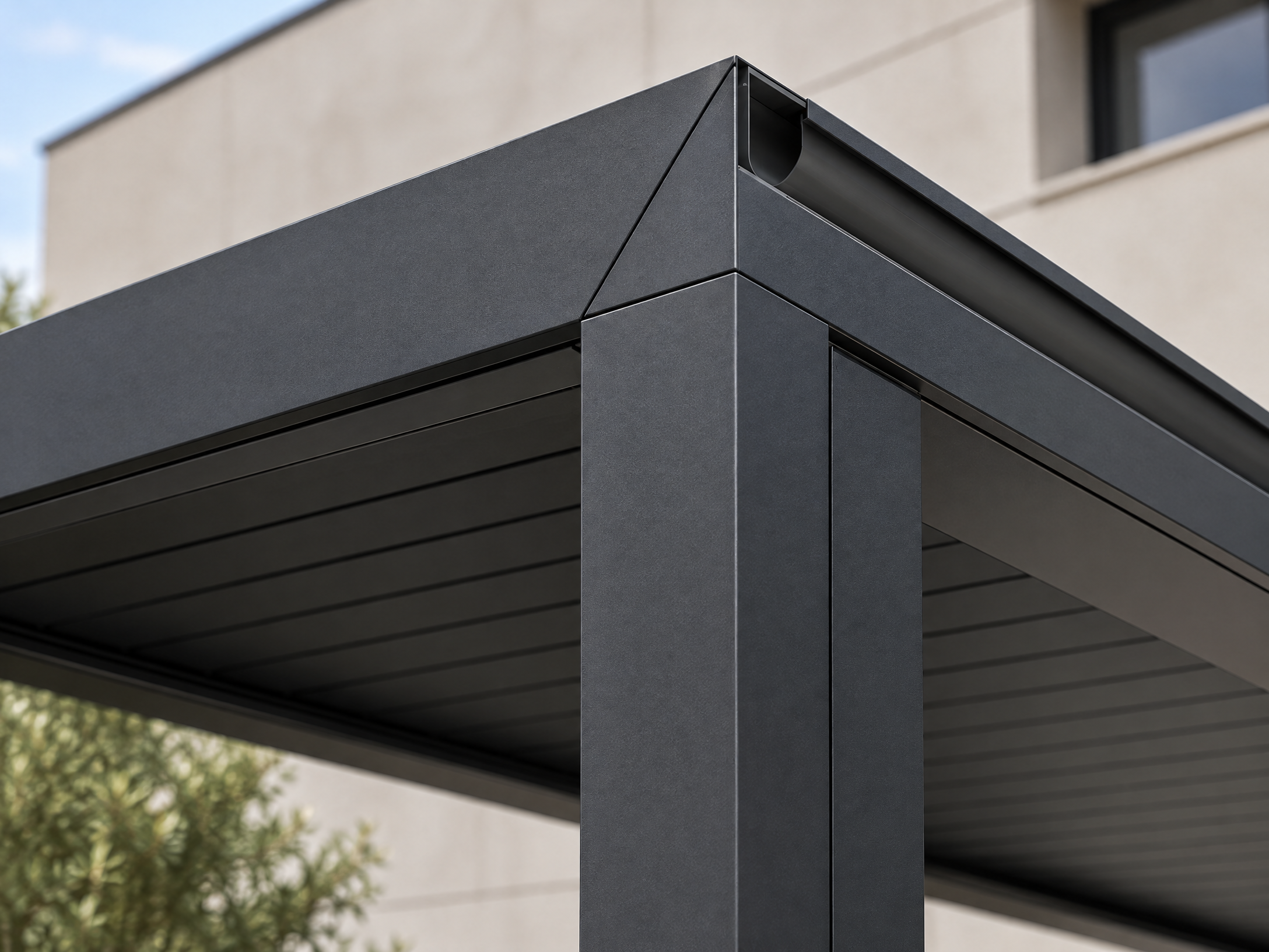
Where a carport has a roof skin or integrated gutter, the joint must preserve water shedding. Request a section showing high/low sides, cover or flexible element, drainage/debris path, seals, fasteners, and access. Use tested or manufacturer-standard details where available; a render is not evidence of suitability.
For long metal panels, the UFGS example specifies that the attachment system permit movement independently of the structure except at indicated fixed points [2]. This reinforces a vital distinction: a waterproof cover may bridge a movement zone, while the component beneath still requires room to move. If a gutter crosses a frame separation, show whether it is independently supported, connected with a flexible arrangement, or divided and drained separately.
Electrical and utility coordination
PV and EV-ready carports introduce conduits, trays, feeds, lighting, and data paths that must not bridge a movement zone. DOE identifies movement and water exclusion as reasons for suitable outdoor conduit fittings [3]. Request the fitting/approved means, supports, cable strain relief, enclosure transition, bonding continuity, and edge protection.
Utility connection requirements are outside a generic carport specification. The utility provider and qualified electrical professionals determine interconnection, metering, protection, grounding/bonding, and equipment requirements. The buyer should set an early coordination gate so no carport joint, foundation, or route blocks later utility work.
| Interface | Questions to place in the specification | Evidence to request before work proceeds |
|---|---|---|
| Steel/aluminum secondary member | Are materials separated where necessary? Is the movement direction free after bolts are tightened? | Detail, material schedule, fastener/isolator data, movement calculation |
| Roof panel to frame | Which clip is fixed and which clips slide? How are end laps and flashings prevented from restraining movement? | Roof layout, clip schedule, section details, installation instructions |
| PV rail to carport subframe | Where are rail expansion joints, fixed points, clamp zones, and bonding links? | Racking layout, manufacturer manual extract, module compatibility confirmation |
| Module to clamp/rail | Can rail movement occur without imposing stress on module frames or moving clamps outside approved locations? | Module installation instructions, clamp layout, torque/inspection record |
| Gutter/downpipe | Does the water path remain continuous without tying independent moving blocks together? | Joint detail, drainage drawing, field water-management check plan |
| Conduit/cable route | Are flexible or expansion provisions, supports, bend radius, strain relief, and weather sealing addressed? | Electrical shop drawing, fitting data, support and inspection plan |
| Civil works at columns | Are paving, curbs, trench lids, and landscape edges isolated from the intended movement behavior? | Civil/structural interface detail and responsibility matrix |
Mid-article CTA: Preparing a multi-package carport enquiry? Send the site location, layout, roof/PV concept, and available drawings to info@carportiva.com, or use the project inquiry form. Ask for a documentation-led review of the movement interfaces to be coordinated with your local qualified professionals.
Require factory, shipment, and installation evidence—not just a drawing note
Fabrication, packaging, erection sequence, and inspection can alter movement behavior. Convert design intent into hold points and traceable evidence for the supplied product and interface.
Request controlled shop drawings identifying member marks, material, connection orientation, fixed/sliding status, slot direction, splices, covers, and preset gaps. Request current manuals for the actual roof, racking, and electrical products—not a generic catalogue. UFGS calls for manufacturer manuals, instructions, and standard details used with approved shops [2].
For mixed metals, request an isolation detail if direct contact could create galvanic corrosion. UFGS calls for a bond break or neutral material where dissimilar-metal contact can cause galvanic action [2]. The project designer must determine its applicability.
Protect long components in shipment, identify installation sequence, and state removal of temporary restraints. At a pre-installation conference, review the movement plan, temperature-dependent settings, gaps, sliding direction, and deviation process. Follow actual product instructions for tightening; DOE notes that mounting-system instructions commonly address mechanical integrity and loading checks [5].
A concise evidence schedule is more useful than a broad “quality certificate” request:
- Before fabrication: approved design basis, interface register, movement plan, responsibility list, product data.
- Before shipment: final shops, IDs, fixed/sliding schedule, packing list, restraint-removal instructions.
- Before installation: current manuals, compatibility information, method statement, inspection plan, electrical coordination drawings.
- At hold points: photos/checks of fixed points, slots, gaps, covers, rail joints, clamps, cable/conduit provisions, drainage, approved changes.
- At handover: as-built movement plan, deviations, inspection records, maintenance information, modification constraints.
Evidence should be legible, dated, tied to a grid location or component ID, and retained with the project file. It cannot replace the authority having jurisdiction or the qualified professionals’ required inspections. The International Code Council explains that codes used by jurisdictions are model codes whose adoption and enforcement are local matters [6]; therefore, final acceptance route and inspection obligations must be confirmed locally.
Run a buyer workflow that prevents late movement conflicts
The following workflow lets a procurement team make thermal movement visible early while keeping final engineering decisions with qualified local professionals.
- Collect project inputs. Establish location, orientation, site climate information, parking geometry, roof/PV concept, carport material choices, structural spans, drainage strategy, utility routes, authority constraints, and expansion of adjacent works. Flag missing data rather than filling it with generic assumptions.
- Map continuous runs and interfaces. Mark primary frames, purlins, roof panels, rails, gutters, conduits, cable trays, signs, lighting, paving, and building tie-ins. Identify every location where unlike components connect or one system crosses another.
- Assign design responsibility. Name the engineer of record and identify who prepares structural, PV-racking, roof, electrical, civil, and drainage details. Create an interface register with one accountable reviewer for each boundary.
- Request the movement design basis. Require the calculation inputs, actual product/material data, temperature premise, fixed points, sliding points, joint travel, installation condition, and any combination with other movement effects.
- Review a coordinated movement plan. Check plan, elevation, and sections together. Confirm that each declared moving component has a path and that no secondary bolt, cover, gutter, module clamp, cable tray, curb, or finish system blocks it.
- Check manufacturer instructions against the design. Review current roof, racking, module, clamp, fastener, sealant, and conduit documentation. Where instructions conflict, stop and obtain written resolution from the responsible qualified parties before procurement or installation.
- Freeze evidence and change control. Put the approved joint details, drawing revision, inspection points, photo requirements, and authority/utility dependencies into the purchase order and construction quality plan. A field substitution must trigger review of movement implications.
- Inspect before concealment and at handover. Verify fixed versus sliding hardware, direction and gap setting, joint covers, PV-rack provisions, electrical pathways, drainage, and as-built records. Record unresolved conditions for the project team and authorities rather than closing them by assumption.
Frequently asked questions about carport thermal expansion joints
Does every carport require visible expansion joints?
No. A carport needs a movement strategy, but the appropriate solution may be sliding clips, guided bearings, a racking-system rail joint, an articulated connection, a separation between independent blocks, or another engineered detail. Whether a visible joint is needed depends on geometry, materials, temperature basis, load system, roof/PV configuration, codes, and local engineering judgment.
Can a buyer specify one thermal expansion coefficient for the whole carport?
That is usually a poor specification. NIST reports materially different typical values for aluminum and steel and notes variation within material classes caused by composition, processing, and temperature range [1]. Require the final calculation to use the actual product material data or a justified engineering value for each relevant component.
Are PV rail splices automatically expansion joints?
No. A splice may be a structural or alignment connection, an expansion provision, or both, depending on its design and installation. DOE advises that rail expansion-joint specifications and positions should be addressed in the racking installation manual or design drawings [3]. Buyers should request the exact product detail and install it as documented; they should not classify a splice by appearance.
How should the specification deal with PV modules near rail movement points?
Require coordination of rail-joint locations, rail fixed points, module clamp zones, approved mounting areas, and module/racking instructions. DOE notes that missing or improperly installed rail expansion joints can force module clamps, while PV installation instructions commonly address mechanical stress and suitable mounting systems [3][5]. The PV designer and qualified installer should confirm the final arrangement.
Is a slotted bolt hole enough to accommodate thermal movement?
Not by itself. Its effectiveness depends on slot orientation and length, connection forces, bolt/washer arrangement, tightening and slip behavior, corrosion protection, clearance, load path, water management, and whether other components still restrain movement. It should be part of an engineered, documented connection—not an ad hoc field modification.
How do electrical conduits affect a movement joint?
A rigid conduit run can bridge a structural movement zone and transfer force to fittings or enclosures if not properly detailed. DOE highlights both thermal movement and water intrusion as reasons for appropriate conduit fittings in outdoor PV installations [3]. The electrical designer, installer, utility provider, and local authority determine the required method and inspection requirements.
Can an overseas fabricator decide the final joint layout?
A fabricator can provide product-specific shop details and documentation, but should not be assumed to decide site-specific code, structural, utility, electrical, drainage, or authority issues unless contractually qualified and authorized to do so. Final decisions belong to the local qualified engineers, installers, utility providers, and authorities with responsibility for the project.
Conclusion
A robust specification for carport thermal expansion joints does not begin with a generic gap dimension. It begins with a map of components, materials, restraints, movement directions, and interfaces. It then converts the project-specific temperature and material assumptions into a documented movement design basis; identifies fixed and sliding points; reconciles the frame with roofing, PV racking, drainage, and electrical pathways; and requires evidence from shop drawing through handover.
For buyers, the most valuable tender requirement is not “allow for expansion” but a coordinated, reviewable submission: the movement plan, calculation basis, actual manufacturer instructions, interface details, installation hold points, and as-built record. This approach makes comparison between proposals more meaningful and reduces the chance that a moving element is inadvertently locked in place by another trade. Local qualified engineers, installers, utility providers, and authorities determine final project decisions and should resolve site-specific requirements before fabrication, installation, or acceptance.
References
- NIST: Uncertainties in Dimensional Measurements Made at Nonstandard Temperatures
- UFGS 07 61 14 Steel Standing Seam Roofing
- U.S. Department of Energy: PV System Owner’s Guide to Identifying, Assessing, and Addressing Weather Vulnerabilities, Risks, and Impacts
- ASCE/SEI 7-22: Minimum Design Loads and Associated Criteria for Buildings and Other Structures
- U.S. Department of Energy: Assessing Fire Risks in Photovoltaic Systems and Developing Safety Concepts for Risk Minimization
- International Code Council: I-Codes adopted in all 50 states and Washington, D.C.
Bring the actual project brief to the engineering table.
Share your location, layout, target application and available technical inputs. Carportiva can help identify the relevant product-interface information before a project-specific commercial discussion.
Request a project discussion